Part Two: Designing Products for Rotational Molding
Draft Angles, Shrinkage & Warpage
Part Two: Designing Products for Rotational Molding
Draft Angles, Shrinkage & WarpageDraft Angles, Shrinkage & Warpage
The term “draft angle” refers to a taper that is applied to the surfaces of parts, perpendicular to the parting line of the mold. A draft angle will make it easier to remove the finished part from the mold cavity.
In order to optimize overall cycle time, the molder will seek to minimize a part’s cooling time. In order to de-mold the part, it must be sufficiently cooled to retain its shape and to resist the forces required to remove it from the mold. Typically, polyethylene parts can be removed from the tool at temperatures lower than 190ºF; at this temperature the material is solid, but still has significantly flexibility. If too much force is required to remove the part, it may become irretrievably distorted. A generous draft angle will reduce the forces applied to the part during removal and induced stress and distortion will be minimized.
Despite the benefit of incorporating draft angles, parts can be rotomolded with no draft angle at all. This is made possible by the tendency of most rotomoldable polymers to experience a significant shrinkage when the hot melt cools to its crystallization temperature. This shrinkage encourages release of the part from the tool. For polyethylene roto grades, this release temperature is approx. 260ºF.
Other rotomoldable polymers that experience significant shrinkage include polyamide and polypropylene. PVC and polycarbonate do not shrink to any appreciable degree.
The shrinkage of polymers will have an adverse effect on release from cores; in this case shrinkage will make release more difficult. For example, a donut-shaped part will shrink away from the mold cavity on its outside surfaces, but will shrink down tightly on the inner surfaces of the shape. In such a case, it would be wise to incorporate a generous draft angle on the inner surfaces.
Of the various rotomoldable polymers, polyethylene experiences the most appreciable shrinkage rate; mold designers typically use a figure of 1-4% for this polymer. Polyamides and polypropylene shrink less: 1-2% is a typical allowance. However, it should be noted that shrinkage and release can be affected by a wide range of factors other than base polymer type:
- Mold surface texture: A high gloss surface should release easier than a textured one. However, avoid over-specification, as excessive mold polishing adds significant cost.
- Permanent tool coating or type of semi-permanent mold release agent used: PTFE coatings can be applied that have a range of release characteristics. Similarly, both high, medium and low release semi-permanents are available.
- Cooling rate: If a fast cooling rate is applied above the release temperature, there may be a quicker release of polymer from the tool surface. However, too fast a release may encourage warping, especially on flat surfaces. The use of water cooling, as opposed to forced air cooling, is known to promote warping.
- Material type: Even amongst the family of polyethylenes, shrinkage rates may vary enough to be noticeable. In general a PE rotograde of higher density will shrink more and, in a non-optimized cooling environment, may warp significantly
- Pigments: Different pigments, added to the polymer to achieve a specific color shade, can have different effects on shrinkage and release. Organic pigments promote early crystallization of the polymer and increased shrinkage; this is especially noiticeable in blue shade pigments. In contrast, whites and pastel shades will tend to shrink slightly less.
- Additives: Some of the additives and processing aids that are incorporated into polymer formulations can have a noticeable effect on shrinkage and warpage.
- Mold design: Polymer laid down more thickly in corners of a mold will cool at a slower rate than that in the middle of a side wall. This can promote a shrinkage behavior where the polymer in the middle releases earlier than that at the corners. In large parts, this can generate a tendency for the side wall to bow inwards from the corners, when the part has cooled down completely.
- Clumsy or aggressive demolding: As previously discussed, over-manipulation of a hot part during demolding can result in a permanent distortion.
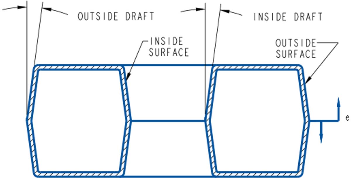
Recommended draft angles (Fig 27) for polyethylene (in º per side) are:
Outside surfaces: Minimum 0º Maximum 1º
Inside surfaces: Minimum 2º Maximum 4º
Textured surfaces: Add 1º/side additional draft for each .001 inch of textured depth
Large parts: Consider increasing draft angles, if possible
Unusual shapes: As above
In conclusion, whilst parts with no draft angles can be produced (especially if ease of processing and part cost are of secondary importance), liberal draft angles should be incorporated into the design of plastic parts wherever possible.