Part Two: Designing Products for Rotational Molding
Wall Thickness Uniformity
Part Two: Designing Products for Rotational Molding
Wall Thickness UniformityWall Thickness Uniformity
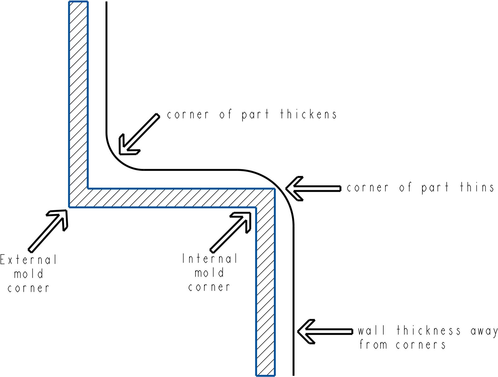
Rotationally molded parts have a tendency for gradually thickening wall thickness on the outside corners of a part and slightly thinner wall thickness on sharp inside corners (Fig 13). In view of this, wall thickness variation is usually understood to relate to variations in wall thickness across wall sections, not including corner sections of the part.
The nature of the rotomolding process results in the thickness of wall sections to be relatively uniform, even with highly complex shapes. Depending on a part’s size and shape and the material being molded, a variation in wall thickness wall thickness tolerance of ±20% would be anticipated, in normal “commercial” rotomolding. This variation can, in principle, be reduced to approx. ±10% with tighter process optimization, but this would usually be accompanied by increased costs, in terms of development time and potential scrap rates.
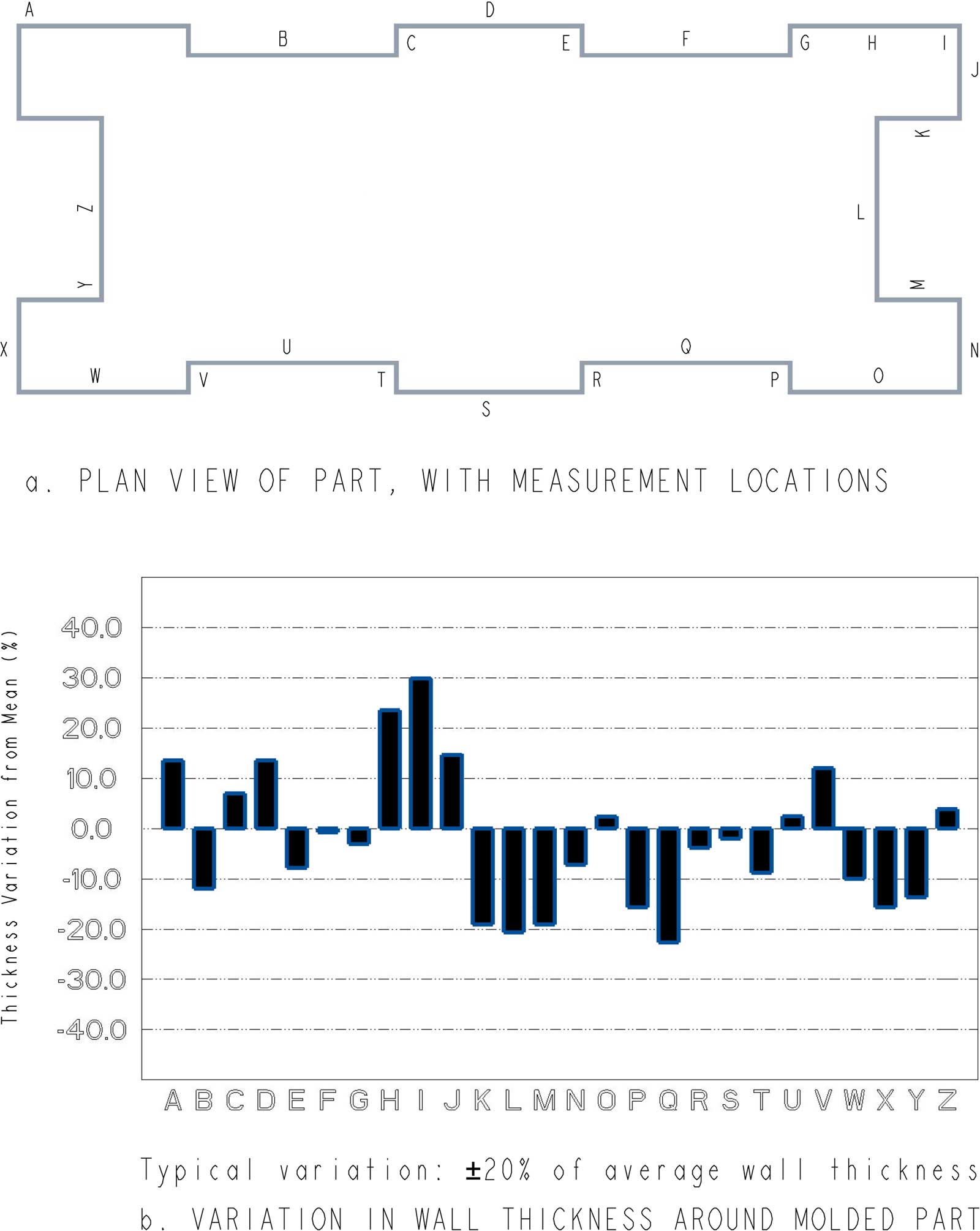
Fig 14 shows measured wall thickness variation around an actual rotomolded part; this further reinforces the point that a ±20% variation is realistic, under standard molding circumstances.
During rotomolding, the biaxial motion causes powder to run across the inside surfaces of the mold in a progressive fashion. The effect of gravity ensures that the powder accumulates in a “pool” of material at whatever portion of the mold is at its lowest point. As the mold rotates, a different area of the mold passes through the powder pool and in this way, every area of the inside cavity should “see” powder at some point.
The heat of the oven causes the outside mold temperature to increase and subsequently heat conducts through the mold wall and the temperature of the inside mold surface also rises. At some temperature (for polyethylene, approx 230͒͒͒°F), the inside wall will be sufficiently hot for powder particles to tackify, to adhere to the wall and to be carried out of the powder pool. This effect continues as other parts of the wall become hot enough and enter the powder pool. In this way, material is gradually extracted from the pool and deposited on the mold wall; eventually the powder pool will become fully depleted of material, which will all be adhered to the wall.
If one area of the mold is pre-heated, prior to the mold being inserted in the oven, it is logical that this area will reach the tackifying temperature sooner than surrounding areas that have not been preheated. It will therefore be likely that the buildup of material in the preheated area will be greater than other areas and the eventual wall thickness will correspondingly be increased locally. There are also devices (heat fins and air amplifiers) that can concentrate more heat in specific areas, during molding; these are commonly used to provide further control to thickness variation.
If an area of the mold is shielded from heat, an opposite effect becomes apparent; shielded areas will accumulate a thinner wall thickness than unshielded areas. Where build-up of material is to be prevented (eg to form a hole or opening in the part), insulation can be attached to the relevant area outside the mold.
Uneven heat application tends to be the predominant factor in most cases of wall thickness variation. This is especially true for simpler shaped molds. The unevenness may be deliberately induced or may be accidental. For example, if multiple molds are crowded too closely on the arm of a machine, adjacent molds may shield each other from heat in some areas.
Another, less frequent, cause of thickness variation relates to mold complexity and powder motion. If one area of the mold goes through the powder pool more often than others, there will likely be a preferential build-up of material. Alternatively, if an area of the mold “sees” powder less frequently, a thin area may occur. This effect can become particularly apparent with some complex shapes. Usually the issue can be resolved in some way, eg re-positioning of the mold or an alteration in rotation ratios.
Large vertical liquid storage tanks are often made deliberately with gradually thickening walls from top to bottom. The hydraulic load in such products will be greatest near the bottom of the tank, so the provision of a greater wall thickness will ensure that stresses do not exceed material capabilities. This type of wall thickness variation is easiest to achieve with a rock and roll arm motion (see “Machines” section).