Part Two: Designing Products for Rotational Molding
Molded-In Inserts
Part Two: Designing Products for Rotational Molding
Molded-In InsertsMolded-In Inserts
Molded-in metal inserts can be incorporated into plastic parts during the rotomolding cycle. The insert is mounted temporarily inside the mold cavity, the mold is filled and closed and the cycle is started. As the plastic powder melts, it encapsulates the insert into the part wall.
It is important to note that, for standard metal inserts in polyethylene parts, there will be no chemical bond between metal and plastic. The bond will be purely mechanical, as a result of the encapsulation.
Inserts can be held in place using a bolt through the mold wall. There are also a range of proprietary mechanical fixings available and steel inserts have been held in place using external magnets.
There are many different types of mold-in inserts available; these include: hex shape, round knurled, square, bonding fasteners, t-nuts, t-serts, geoserts and custom configurations. Insert selection should consider the forces that will be applied during part usage, including static and dynamic torque, tensile, rotational torque, axial torque, peel, vibration and thermal conditions.
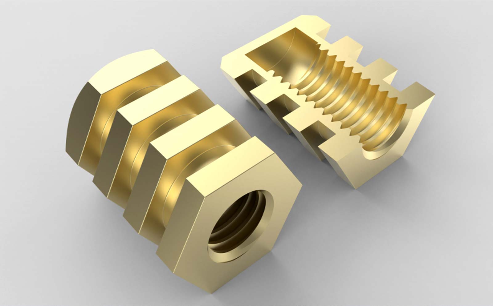
Environmental and operating conditions will dictate choice of the material from which the insert is manufactured. Ideally, insert materials should be capable of rapidly absorbing process heat; this will encourage plastic to melt and accumulate around the insert. Preferred insert designs provide undercuts, ridges or even external mesh components, which all assist in a solid encapsulation by the plastic (see Fig 36).
Fiber reinforced nylon (injection molded) fittings have been used in pressure tanks, to provide a solid threaded opening. The polyethylene powder will melt at a temperature that is considerably lower than the melting temperature of the fitting and will encapsulate it.
Many inserts have internal threads. Common threads are SAE, Metric, NPT, SAE and BSPP. It is also common to mold in non-threaded sleeves and bushings, to act as pass-throughs or compression limiters.
Care should be exercised in selecting the size, shape and location of inserts. As the plastic material cools and shrinks, it draws down tightly on to the inserts, which normally will have a lower coefficient of thermal expansion. This may set up sufficient internal stresses to promote stress cracking of the plastic around the insert. Large inserts tend to be more troublesome in this respect than small ones. Inserts with sharp edges may also encourage stress cracking.
When more than one insert is required, the distance between them should be kept as small as possible. Significant shrinkage of the plastic, between widely spaced inserts, may cause high stress at the interface between the insert and the plastic, promoting a degree of delamination. This condition can also result in difficulties in removing the finished part from the cavity. Multi-insert rings and strips can provide dimensional consistency by resisting the stresses caused by plastic shrinkage. Another option would be to interrupt the cooling cycle once the plastic has solidified (for polyethylene, around 240ºF), release the insert fixings and then continue cooling to the part demolding temperature (usually 190ºF or lower).
One of the advantages of rotomolding is that it is a low-pressure process; this is helpful in preventing the generation of high forces that will deform or break inserts (this can be a problem in injection and compression molded parts).
Components made from plastics (including polyethylene) have been used in some circumstances. For example, baffle walls cut from high density extruded sheet have been held in place inside the mold prior to the start of the process. During cooking, the plastic powder melts and fuses to the sheet, producing a solid welded bond. This requires a high degree of process control and the use of a polyethylene grade for the sheet with a slightly higher melting point than the powder material.